Sherline Help Sheets, Instructions & Diagrams
 Mill & Terminology
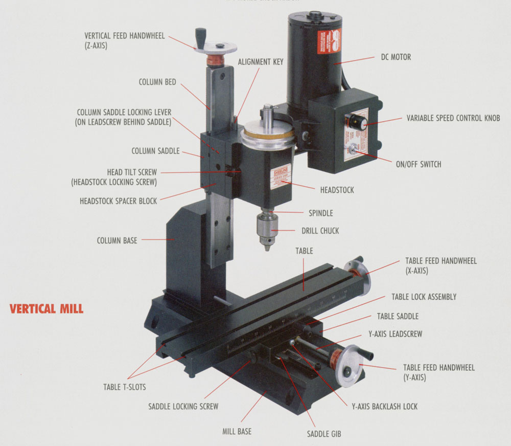
Variable Speed Control Knob—Controls motor speed from 0 to 2800 RPM
Headstock—Contains the spindle in two preloaded ball bearings.
Spindle—The spindle is inside the headstock and is driven with a belt running from the motor pulley to a pulley on the rear end of the spindle shaft. The nose of the spindle is treaded on the outside to receive chucks and tapered on the inside to receive other accessories.
Drill Chuck—Used to hold drill bits for drilling holes. (Not to be used to hold end mills!)
Mill Table—Parts are fixed to the table using a vise, chuck or clamps and moved under the milling cutter using the X- and Y-axis handwheels.
Mill Saddle—The mill saddle slides in and out (Y-axis) on the mill base. The mill table moves left and right (X-axis) on top of the saddle.
Headstock Saddle—The saddle on the vertical column that moves the headstock (Z-Axis) up and down by means of a leadscrew and handwheel.
Mill Column—The steel dovetailed column that is held to the mill column base and supports the Z-axis saddle and headstock.
Leadscrew—The threaded screws that move the table left/right and in/out as well as the vertical axis up and down. They are driven by handwheels marked in .001″ or .01 mm increments.
Leadscrew Locking Lever—Located on the back side of the vertical column, this locking lever locks against the saddle nut to prevent unwanted movement of the Z-axis during machining operations. Manual machines are fitted with a standard on/off locking lever. CNC machines are fitted with an adjustable locking lever that can be used to control backlash in the Z-axis. This function is available as an option on any manual mill as well. (P/N 4017U inch or 4117U metric)
Gibs—Tapered plastic gibs are used on each dovetailed axis to take up wear as it occurs. They are slightly wedge shaped. As side-to-side “slop” develops on an axis, the gib lock is loosened and the gib is pushed a little further into the gap, taking up the play. These allow the machine to always be kept as tight as the operator desires. If or when they wear out, they are very inexpensive to replace.
Mill Base—The solid base that has the dovetail for the saddle to move in and out on and to which the mill column is attached.
Drawbolt—Goes through the hole in the spindle to draw chucks and other accessories into the headstock taper inside the spindle. A special washer locates in on center in the spindle hole.
#1 Morse Arbor—The arbor screws into the back of the drill chuck so it can be used in the headstock. It is held in place in the #1 Morse taper with the drawbolt.
Tommy Bars—Round steel bars used to tighten and loosen chucks and other spindle accessories. Sometimes called “Spindle Bars.”
Y-axis Locking Screw—A thumbscrew on the side of the base that keeps the saddle from moving in and out when tightened.
X-axis Locking Screw—A screw that goes through the barrel lock on the front of the saddle to lock the table in place during machining operations where movement is not required or desired.
Backlash Locks—The lock works like tightening two nuts against each other on a threaded shaft to reduce play in the threads. Backlash is the pause in travel when changing direction of rotation of any threaded crew. Because both sides of the thread don’t rub on the nut at the same time (they would quickly wear out), one surface is pulling or pushing the nut when the screw is turned. When you stop and change directions, the screw turns a slight amount while the thread picks up the other side and begins to move the nut in the other direction. The looser the fit of the threads, the more “backlash” occurs. In essence, it is the amount you can turn the handwheel in the reverse direction before movement occurs on an axis.. An adjustment is provided on the X- and Y-axes to reduce the leadscrew backlash. Backlash is not a “fault” of a machine, it is simply a physical reality that must be taken into account when machining. You adjust to a known or acceptable amount using the locks and then remove it from the machining operation by always approaching your cut from the same direction with the backlash already eliminated before the cut begins.
Alignment Key—A precision ground key that fits in a slot in the column saddle to keep the headstock aligned straight up and down. A second slot is also provided to locate the headstock at 90° for horizontal milling. Removing this key and rotating the headstock allows bevels to be cut at any angle. An approximate angle scale is laser engraved into the saddle for reference.
Headstock Spacer Block—Moves the headstock 1.25″ further out from the saddle to increase the “throat” distance (distance between cutter and column). It is optional on 5000-series mills, standard on 5400-series mills and not needed on 2000-series mills because the ram can be used to adjust this distance.
V-belt—A Kevlar-reinforced Urethane belt that drives the spindle through the pulleys.
2-position Pulley—The normal (rear) position gears the motor down about 2:1 for a maximum speed of about 2800 RPM. The “High Torque” position (closest to the headstock) gears it about 4:1 for lower speed but more torque when needed for heavy cuts.
Column Ram—On the 2000-series mills, a “ram” is added that allows the entire column to be moved in and out and swung from side to side. It is designed based around the movements of the machine shop workhorse—the Bridgeport® mill.
Rotary Column Attachment—This function allows the vertical column to be rotated from side to side to do angled milling or drilling. It is included in the design of the 2000-series mills or can be added as an option (P/N 3700) to 5000/5400-series mills.
Adjustable “Zero” Handwheels—On base model machines, plain handwheels are used. They are laser engraved with 50 marks (inch) or 100 marks (metric) and numbers for reference. Adjustable zero handwheels allow you to stop at any given point, loosen a knurled wheel in the center of the handwheel and rotate the laser engraved collar back to the zero mark before starting the next cut without moving the position of the handwheel. This means each time you are starting from zero rather than from a random number, making your depth and cut calculations easier. This eventually means less mistakes. 4400- and 4500-series lathes and 5400- and 2000-series mills include these upgraded handwheels as standard equipment.
DRO—Stands for “Digital Readout”. Digital readouts incorporate an electronic box with a screen that reads out numbers rather than looking at the graduations on the handwheels to determine movement. If offers two advantages: For those with poor eyesight it is easier to read than the little marks on the handwheel and 2) It keeps track of accumulated distance so you don’t have to count handwheel revolutions when making longer movements. This helps eliminate a common source of errors. Any Sherline lathe or mill can be ordered fitted with DRO or it can be added later. Also incorporated in the readout is a sensor and RPM indicator for the spindle to eliminate guesswork regarding spindle speed.
CNC—Stands for “Computer Numeric Control.” Instead of you turning the handwheels, a computer determines the speed and distance and drives DC motors called “stepper motors” or “servos” to move the lathe for you. Any Sherline machine can be ordered ready for the application of CNC or as a complete CNC system with steppers, controller, computer, software and everything. CNC can also be fitted at a later date to any Sherline lathe or mill.
4th Axis—In milling, in addition to the X-, Y- and Z-axis, the 4th axis is called the A-axis or rotary axis and is provided by an optional rotary table. Sherline offers manual (P/N 3700) or CNC (P/N 8700 or 8730) rotary tables.
End Mills—They look like drill bits but are sharpened on the sides as well as the ends. Held in an end mill holder, they are used to cut slots, pockets or surfaces. End mills are normally flat but “ball end” mills are also available that have a round end for leaving a radius in the corner of a pocket or a round bottomed slot. End mills can have two, three or four flutes (spiral cuts) in the sides. Generally less flutes are better for softer materials like aluminum because they don’t clog as easily while more flutes (and slower cutting speeds) are better for steels that don’t allow as aggressive a cut and produce less chips per cut.
Fly Cutter—A mandrill holds a 1/4″ square shank HSS or Carbide cutter and spins it in a large circle (about 1-1.5″). The part is moved under the cutter which puts a nice, flat surface on the part. Each successive cut overlaps the previous by about 1/3 of the cut until the surface is done.
Mill Vise—A small vise that is clamped to the mill table and holds parts for milling. It is different from the more common drill press vise in that it tightens with a pull-down function that helps hold the part down as well as in to counter the forces of milling. It is also accurately machined so it can be aligned in the machine for accurate cuts.
Hold-down Set—A series of adjustable clamps that are used to hold parts to the mill table for milling. They can be used on large or uneven parts like castings.
Boring Head—Rotated in the headstock, the boring head holds a sharpened tool that rotates off center to scribe a circle. It is lowered into the bore of a hole to enlarge the hole to a given size. A fine adjustment on the boring head allows the cutter to be moved out a little at a time to enlarge the circle of the cut. It is used when a very accurate hole is needed, like on the cylinder of an engine or when a large drill of the needed size is not available or practical. With the boring head you can make accurate holes up to 1.75″ in diameter on a small mill.
Chucks—A 3-jaw or 4-jaw chuck threads onto the spindle nose to hold your work, a drill chuck is used on the tailstock to center drill your part.
Tool Post—Attaches to the lathe table and holds a 1/4″ square cutting tool
Crosslide table—Also sometimes spelled “cross slide,” it is the table with two T-slots that holds the tool post.
Crosslide Gib—A tapered plastic wedge that is held in place by a gib lock. It fits between the angled surfaces of the dovetail and is used to adjust for wear. As wear occurs and the table develops “slop,” the lock is loosened and the gib is pushed further into the gap, taking up any play. This allows the machine to always be kept in peak adjustment.
Tailstock spindle—Has a #0 Morse internal taper for holding chucks and other tools. A handwheel moves it in and out for drilling.
Tailstock locking screw—Locks the tailstock in place on the bed to keep it from moving. When loosened, the tailstock can be slid up and down the bed.
Bed—The dovetailed steel bar that the saddle and tailstock are moved back and forth on.
Saddle—The part that supports the crosslide table and is moved up and down the bed using the leadscrew handwheel.
Saddle Gib—Functions like the crosslide gib to keep the saddle in tight adjustment against the dovetailed bed.
Tailstock Gib—A brass part attached to the base of the tailstock that runs on one of the bed dovetails. The brass part is expected to wear rather than the more expensive bed and can be adjusted for tightness as it wears.
Lathe Base—The cast metal base upon which the lathe bed and headstock sit.
Drawbolt—Goes through the hole in the spindle to draw chucks and other accessories into the headstock taper inside the spindle. A special washer locates it on center in the spindle hole.
#1 Morse Arbor—The tailstock drill chuck normally has a #0 Morse arbor threaded into the back of it for use in the tailstock spindle. That arbor can be removed and replaced with the #1 Morse arbor so the drill chuck can be used in the headstock.
Dead Centers—#1 and #0 Morse arbors have a 60° point and are used to locate and hold work “between centers” on the lathe. The #1 Morse arbor rotates with the headstock, but because the tailstock spindle does not rotate, the rear #0 Morse arbor is called a “dead” center. This needs to be kept lubricated because it creates friction with the moving part it is locating. Most machinists eventually replace this with a “live” center that turns on a ball bearing.
Faceplate—A cast plate that threads onto the spindle nose. A workpiece can be bolted to it as an alternative to using a chuck. It has three slots to drive a drive dog.
Drive Dog—Also called a “Lathe Dog,” this part is attached to a piece of bar stock by means of a screw that goes through the side and the long point is placed into one of the slots in the faceplate. The part is located between the lathe centers (live or dead) and when the faceplate turns, the dog actually drives the piece to rotate it for cutting. It also acts as a universal joint when turning a part between centers when the headstock is rotated to a slight angle, allowing a tapered part to be cut.
Alignment Key—A precision ground key that fits in slots in the top of the bed and bottom of the headstock to keep the headstock aligned straight with the tailstock. Removing this key and rotating the headstock allows tapers to be cut.
Compound Slide—A device found on many lathes that allows the cutting tool to be brought into the part at an angle for cutting tapers. A compound slide is optional on Sherline lathes, but is not included as standard because the rotating headstock feature allows a Sherline lathe to cut tapers without the use of a compound slide. The optional compound slide is P/N 1270 (inch) or 1280 (metric).
Assembly & Maintenance
- Assembling the Headstock, Motor and Speed Control…
- DC Motor Wiring…
- Aligning the Lathe Headstock and Tailstock…
- Gib Installation and Adjustment…
- Saddle Nut Replacement…
- Preload Nut Adjustment and Pulley Adjustment…
- Aligning a Mill…
- Adjusting Leadscrew and Handwheel Backlash…
- Mill Z-Axis Backlash Support Screw Installation…
- Installing New Motor Brushes in the DC Motor…
- Lubrication…
- Adding a Reversing Switch to the Speed Control…
- Straightening an Out-of-Square Motor Mount Bracket…
- Installing Sherline Digital Readout Handwheels on Stepper Motors…
- Changing the Direction of the X-axis Digital Readout…
- Grinding Your Own Lathe Tools…
- Installing Stepper Motor Mounts on a Lathe…
- Installing Stepper Motor Mounts on a Mill…
- Making Your Own Gravers…
- Using a Rotary Table…
- Programming and Using a Sherline CNC Rotary Indexer…
Sherline Lathes
Sherline Mills
- 5000 and 5400 Series Manual Mills
- 2000 Series 8-Direction Manual Mill
- 5000 and 5400 Series CNC-Ready Mills
- 8540/8541 CNC Deluxe Mill (with stepper motors)
- 8020/8021 CNC 8-Direction Mill
Instructions for Using Lathe Accessories
- 1040-3-JAW CHUCKS
- 1072-Sherline Jacobs Drill Chucks
- 1074-STEADY REST
- 1075-4-JAW SELF-CENTERING CHUCKS
- 1080-SHERLINE Compound Slide
- 1090-FOLLOWER REST
- 1160-WW Collets, Sets and Mill Collets
- 1164-COLLET FIXTURE
- 1182-SHERLINE Bullnose live center
- 1185-VERTICAL MILLING TABLE
- 1191-SHERLINE Live Center
- 1201-ADJUSTABLE TAILSTOCK TOOL HOLDERS
- 1202-SHERLINE Adjustable Tailstock Chuck Holder
- 1203-SHERLINE Adjustable Tailstock Tool Holder
- 1206-SHERLINE Adjustable 1″ Die Holder
- 1220-TAILSTOCK SPINDLE EXTENDER***
- 1270-COMPOUND SLIDE
- 1291-RISER BLOCKS
- 2000-SHERLINE MODEL 2000 MILL COLUMN
- 2049-SPINDLE HANDWHEEL
- 2085-WW COLLET ADAPTER
- 2090-CLOCKMAKER’S ARBORS & POT CHUCKS
- 2100-2090-CLOCKMAKER’S ARBORS & POT CHUCKS
- 2110-W.R. SMITH T-REST
- 2125-Installing a Protective Glass Filter on the Microscope Lens
- 2125-Lathe Microscope Mount
- 2127-Mill Microscope Mount
- 2200-RADIUS CUTTING ATTACHMENT
- 2250-QUICK-CHANGE TOOLPOST AND TOOL HOLDERS
- 2256-USING CARBIDE INSERTED TIP TOOLS
- 2258-INSERTED TIP CARBIDE TOOLS
- 2261-INSERTED TIP CARBIDE BORING TOOLS
- 2265-INSERTED TIP CERAMIC TOOL HOLDER
- 3001-POWER FEED
- 3002-CUT-OFF TOOL AND HOLDER
- 3004-KNURLING TOOL AND HOLDER
- 3005-GRINDING YOUR OWN LATHE TOOLS
- 3006-USING CARBIDE INSERTED TIP TOOLS
- 3007-GRINDING YOUR OWN LATHE TOOLS***
- 3009-TOOL HEIGHT GAUGE
- 3016-REAR MOUNTING BLOCK
- 3018-REAR MOUNTED CUT-OFF TOOL HOLDER
- 3038-WOOD TOOL REST
- 3050-VERTICAL MILLING COLUMN
- 3100-3.5″ Lathe Thread Cutting Attachment
- 3420-RESETTABLE HANDWHEELS
- 3580-8-DIRECTION VERTICAL MILLING COLUMN
- 3701-RIGHT ANGLE ATTACHMENT FOR 4″ ROTARY TABLE
- 4360-CHIP GUARD
- 4417-CNC Lathe Leadscrew Backlash Lock
- 5335-Sherline Lathe Basics—Setup and Use of the Sherline Lathe
- 7600-CARBIDE CUTTING TOOL INSERTS AND HOLDERS
- 7610-3/8″ IC 55° NEGATIVE RAKE INSERT TOOL HOLDER
- 7620-CARBIDE INSERTED TIP FLY CUTTER
- 8200-LATHE DIGITAL READOUT
Instructions for Using Milling Machine Accessories
- 1012-SENSITIVE DRILLING ATTACHMENT
- 2045-INDEX BLOCK SET
- 3012-MILL HOLD-DOWN SET
- 3013-STEP BLOCK HOLD-DOWN SET
- 3049-BORING HEAD
- 3052-FLYCUTTER AND SLITTING SAW HOLDER
- 3054-BORING HEAD
- 3055-MORSE #1 BLANK
- 3060-MILLING COLLETS
- 3200-INDEXING ATTACHMENT
- 3500-ROTARY COLUMN ATTACHMENT
- 3551-MILL VISE
- 3560-MILL TOOLING PLATE
- 3570-ROTATING VISE BASE
- 3750-TILTING ANGLE TABLE
- 4017-Model 2000 Mill Upgrade Installation Instructions
- 4335-10,000 RPM Pulley Set
- 5011-MILL X AND Y BACKLASH UPGRADE
- 5650-8-DIRECTION MILL UPGRADE
- 6100-HORIZONTAL MILLING CONVERSION
- 6101-MILLING COLUMN CONVERSION
- 6700-INSTALLING CNC STEPPER MOTOR MOUNTS ON A SHERLINE MILL
- 6720-INSTALLING CNC STEPPER MOTOR MOUNTS ON A SHERLINE LATHE
- 8100-Mill Digital Readout
- 8700-CNC ROTARY INDEXER
- 8800-CNC LINEAR CONTROLLER
- 8850-CNC MILL POWER FEED
- 8900-HIGH SPEED ENGRAVING HEAD
- DC Motor Wiring
- Changing DC Motor Brushes
- DC Motor Assembly and operation
Instructions for Kits
- T1000—”Turner’s Cube” machinist’s puzzle kit, Includes raw materials plus required tools (except 4-jaw self-centering chuck)
- T1076—Same as above but includes P/N 1076 4-jaw self-centering chuck in kit
Instructions for Chucks
Instructions for Rotary Tables
- Sherline 3700 Rotary Table Instructions
- Sherline 3701 Rotary Table Instructions
- Sherline 3750 Rotary Table Instructions
- Sherline 8700 Rotary Table Instructions
Exploded Views and Diagrams
- SHERLINE MODEL 2000 MILL COLUMN
- 8-DIRECTION MILL P/N 2000
- SHERLINE CNC-READY VERTICAL MILLING MACHINES
- SHERLINE VERTICAL MILLING MACHINES EXPLODED VIEW AND PART NUMBER LISTING
- Mill Digital Readout P/N 8100
- Installing CNC Stepper Motor Mounts On A Sherline Mill
- SHERLINE CNC-READY 8-DIRECTION VERTICAL MILL EXPLODED VIEW AND PART NUMBER LISTING
- SHERLINE Mill Digital Readout
- VERTICAL MILLING MACHINE OPERATION
- Mill Specifications
- Milling Machine Terminology
- SHERLINE 8-Direction Mill
Sherline Part Numbers
- SHERLINE CNC-READY LATHE EXPLODED VIEW AND PART NUMBERS
- Installing CNC Stepper Motor Mounts On A Sherline Lathe
- FULL ONE YEAR WARRANTY on Sherline’s 3.5″ Metal Lathe
- SHERLINE Lathe Digital Readout
- SHERLINE LATHE EXPLODED VIEW AND PART NUMBER LISTING
- SHERLINE Lathe Operating Instructions
- SHERLINE Lathe and Mill Setup Instructions
- Lathe Specifications
- Lathe Terminology